|
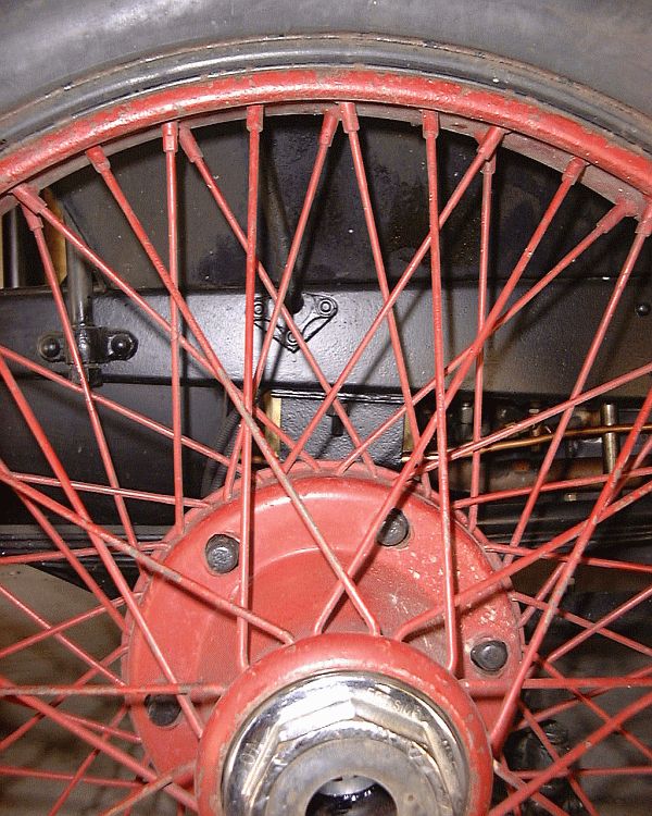
The close-up photograph above provides an idea of what the wire wheels looked like before restoration activities commenced. The oval hub holes are clearly visible in this photograph. Careful observation will reveal the pitting that was painted over in the first restoration in the early 1950s and the pitting that has occurred since. A replacement spoke was added at the two o'clock position as evidenced by the smaller diameter. The nickel plating of the hub nut is chipped and the Stanley logo hub cover is missing. The pitting of the rim is light for this wheel compared to some of the other wheels. The white splatter on part of the center hub is paint from ages ago. The first activity was to research the web for any information describing how to respoke a wheel. Numerous articles exist on how to do bicycle wheels and motorcycle wheels but really nothing could be found at the time regarding automotive wire wheels. Research did turn up Dayton Wire Wheel however as a company that provides wire wheel restoration for automotive wheels. In reading the through the information on respoking bicycle and motorcycle wheels the first thing that became evident was that before any spokes are removed, the existing spoke pattern must be documented.
The first thing that had to be done was to document the spoke pattern. To do this the worst wheel of the group was "sacrificed". The plan of attack called for disassembling of the wheel to get spoke samples as well as using it for documentation and a trial respoking before attempting to do the remaining four wheels. One of the techniques used to document the spoke pattern was to create a CAD drawing of the hole pattern. In the photo above of the CAD drawing the inner circle of green diamonds represents the holes at the rear of the hub where the spokes angle off to the left. The circle of red diamonds represents the holes for the spokes at the rear that angle off to the right. The circle of light and dark blue diamonds represent the double row of holes at the front (or nut end) of the hub. The large inner circle of gray diamonds represents the front single row of holes for the spoke nipples in the rim while the violet and orange circles of diamonds represent the rear rows of holes. The green line represents the valve stem hole in the rim and marks the start-end for counting holes.
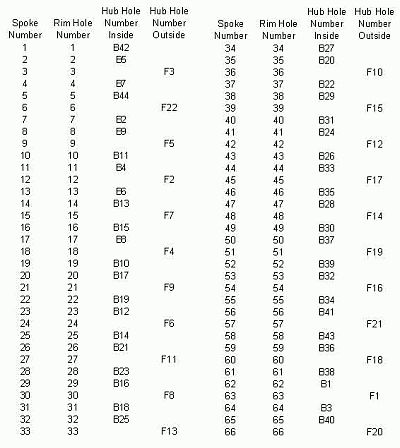
To further document the spoke pattern a Microsoft Excel spreadsheet was generated. The CAD drawing identified the hole patterns and provided for a unique identifier for each hole. The spreadsheet thus identified each spoke by number and indicate the rim and hub holes it was connected between. Thus, for example, spoke 24 was connected between rim hole #24 and hub hole F6 (the front or nut end of the hub and hole #6). With documentation in hand of how the wheels were spoked the next step was to remove some spokes for replacement. The tire was removed from the rim which turned out to be a difficult task. Years of moisture had badly rusted the tire side of the rim making sliding the tire, tube, and flap off the rim very difficult. With the tire removed an attempt was made to back the ferrules off a couple of the better spokes. When the flats on the ferrules rounded off under the wrench a pair of vice-grips was tried and that only served to twist the spoke. Selected ferrules were heated with an oxygen-acetylene torch to cherry-orange heat, allowed to cool, the reheated several more times. This allowed the use of a 7mm wrench to turn the ferrule off the wire spoke. The spoke could then be removed. A total of 12 spokes were removed, two in each direction of lacing, and from all three lacing positions of the rim to insure that sufficient spokes were available to serve as replacement samples.
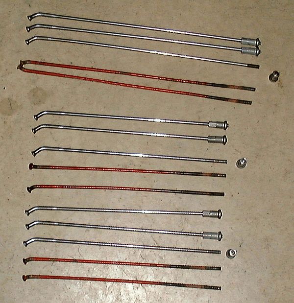
The photo above shows the original spokes (in red) that were removed from the wheel as samples to send to Dayton and the replacement spokes that Dayton supplied. Dayton Wire Wheel manufacturers spokes in addition to providing complete restoration activities. Samples of the spokes were sent off to Dayton for an estimate of the costs to provide spokes. The spokes used originally were tapered at both the head end as well as the ferrule end. Unfortunately the only spokes that Dayton could supply were spokes with the taper at the head end. In addition the Dayton replacement spokes and ferrules would be slightly larger than the originals which would require drilling out the holes in both the hub and rim. Dayton provided a small 5" long sample spoke for evaluation. |