|
The speedometer system for the car was supplied by Warner after their merger with Stewart to become Stewart-Warner (Stewart and Warner merged in 1912). Arthur P. Warner founded the Warner Instrument Company in 1904 to make clocks and speed recording devices for cars. Among his 100 inventions was the magnetic speedometer which is the design commonly used. The magnetic or mechanical speedometer was the most complex to manufacture but it also was the most accurate. Warner's design was based on a spinning permanent magnet inside an aluminum housing. Driven by a flexible cable, the magnetic flux currents tried to spin the aluminum housing in the direction of the magnet's rotation while the housing was being held back by a weak spring. The movement of the disk with speed indication numbers representing miles per hour around its outer circumference provided the indication of speed. The same drive that rotated the magnet was also coupled to an arrangement of gears which drove cylinders with numbers imprinted on the exterior. The numbers indicated the distance the vehicle had traveled in miles. As all speedometers were the same internally but different automotive manufacturers used different wheel diameters the coupling at the wheel allowed for interchangeable gears. By installing the proper gear ratio the speedometer could be made to read the proper speed and record an accurate mileage. Measuring a vehicle's speed through the transmission was not done until later years. Part of the problem rested in being able to design a flexible cable to transfer the wheel's rotation to the back of the speedometer unit. The early flexible speedometer cables actually had a series of chain links inside what transmitted the rotational information between the front wheel and the speedometer. The speed was thus measured from one of the front two wheels since these wheels were closest to the speedometer. It wasn't until the flexible wire cable was developed that longer cables could be used and connections made to the transmission.
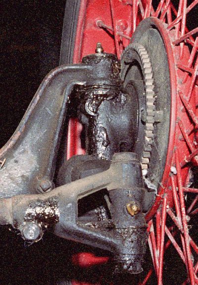
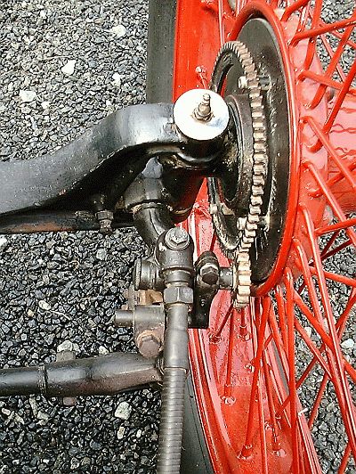
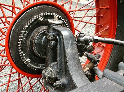
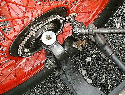
With measuring the vehicle speed by monitoring one of the front wheels the problem of the turning of the wheels for steering had to be accommodated. The solution was to incorporate a swivel drive at the wheel. The swivel drive allowed a fixed connection between the drive gear on the wheel hub and the input gear to the swivel drive. The swivel drive was designed in such a way that the swivel drive moved with the wheel assembly for steering the car but the flexible cable containing the chain drive was allowed to swivel and thus the cable would remain relatively stationary. The swivel drive that transformed rotations of the wheel into rotations of the flexible speedometer cable was not in place when the car was purchased. Only the gear was mounted to the front right wheel. The speedometer swivel drive and cable had been removed long ago and was part of a box of parts the came with the car. There was no fiber gear on the swivel drive to mesh with the gear mounted to the back of the wheel hub. Turning the swivel drive's shaft by hand revealed there was no rotation of the speedometer cable.
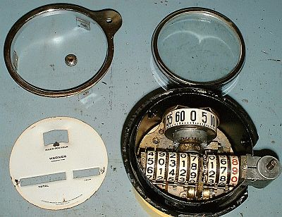
The Warner combination speedometer and odometer was still mounted in the car's dash. It appeared to be operational but once removed from the dash, turning the input shaft with an electric drill motor did not generate any speed indication or change of mileage. So not only was the speedometer and odometer drive in need of repair it appeared the speedometer unit would need repair as well. When taking the speedometer unit apart it was interesting to note that the maximum speed the unit will indicate is 60 miles per hour. In 1918, considering road conditions and the general mechanical design of the vehicles (mechanical steering, poor brakes, wooden spoke wheels, limited spring and shock absorber technology, etc), anyone driving 60 miles per hour was probably already late for a fatal accident if they weren't already in the midst of one! The speedometer swivel drive was disassembled and found packed with hard, dried grease. The internal gear train was originally manufactured of “pot metal” or "white metal". Pot or white metal was a common material used for castings at the beginning of the 20th Century before the advent of plastics. A combination of lead, zinc, and small amounts of other metals such as copper and tin. As pot metal gets brittle with age the added resistance of the dried grease destroyed the gear teeth. All of the internal gears would need to be replaced.
To understand the condition of the speedometer it was opened for inspection. The main drive spindle into the unit included pot metal gearing and it too had deteriorated. The internal gear trains for the odometer and the trip odometer appeared to be in serviceable condition however the speed indication wheel was not free to move. Thus the speedometer was going to require the attention of a professional restorer with knowledge and replacement parts.
The speedometer, the swivel drive, and the flexible drive cable were shipped off for a full restoration. The restoration involved the machining of replacement steel gears for the swivel drive and the speedometer. The flexible drive cable had the internal chain link drive removed and a modern round flexible drive cable installed. The original drive cable shield was large enough that the replacement flexible cable and its flexible housing all slid easily into the original drive cable shield. Along with the speedometer was sent the outside diameter measurement of the car’s tires and the diameter and number of teeth on the speedometer drive gear mounted to the front right wheel hub. Thus part of the restoration involved insuring the speedometer displayed the proper speed and odometer readings for the vehicle. As the proper calibration of the speedometer relied on the proper fiber gear being installed on the swivel drive, several gears were supplied for the reinstallation and future use (the fiber gears wear and should the drive lock up a shear pin breaks to release the fiber gear from the swivel drive).
As removed from the car the odometer displayed 98,058 miles. It is unknown if the car actually had this mileage on it. It is known that the previous owner indicated the speedometer quit working sometime “years ago” and that he had no idea of how many miles he had put on the car with the odometer not functional. He guessed it might be in the 10,000 miles range; maybe as high as 15,000. When the speedometer was rebuilt the odometer was set to 50,000 miles as other Stanley owners commented that this was perhaps a more reasonable mileage for a Stanley. The original mileage displayed on the unit was marked on the back of the face dial during restoration for future reference. An interesting advertising point often made by Stanley was that their cars only had 13 moving parts in the engine and 37 moving parts on the complete car. They obviously ignored the speedometer and odometer as there's nearly that many in this single component of the car! While the Stanley was in Florida in 2006 for the Centennial Celebration of the Stanley World Speed Record at Ormond Beach an opportunity presented itself to check the accuracy of the speedometer. Using Garmin®'s nRoute GPS software operating on a Toshiba Satellite notebook computer the speed of the Stanley as it traveled the coast highway (Highway A1A) was monitored. The speedometer's displayed speed was just shy of 5 MPH lower than what the GPS system indicated the car's speed to be. The speedometer indicated 34 MPH and the GPS system indicated a vehicle speed of 38.9 MPH. |