|
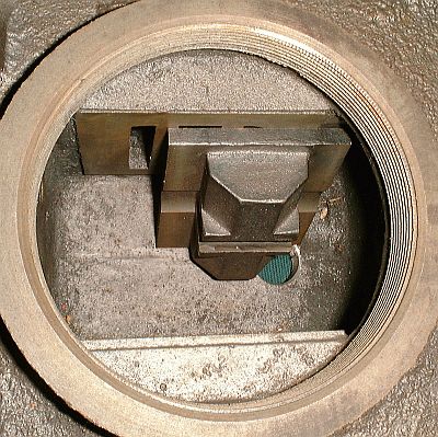
This is a close-up photo of the valve chamber (sometimes referred to as
the valve chest) as viewed through the access port. The
crankshaft would be to the left (rear of the car) and the engine mounting
strap to the right (front of the car). The D-slide valve is sitting
in position against the valve seat for the right cylinder as the engine is
mounted in the vehicle (this picture is what you would see if you were
laying under the engine looking up into the valve chamber ~ thus right is
at the top and left is at the bottom). The half-circle hole to the
lower right of the valve is where the steam supply enters the valve
chamber. A second D-slide valve would be located opposite the valve
shown. The valve rod would be positioned through the valve chamber
from left to right in the photo and would intersect with the slot that is
in the D-slide valve.
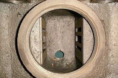
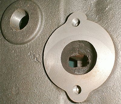
This view is looking directly into the valve chamber with no D-slide
valves present. The vertical surfaces are the valve seats for each
cylinder. The large rectangular opening in each valve seat is for
the steam exhaust to exit the engine. The two small rectangular
openings either side of the large opening are ports to the ends of the
cylinders. The circular hole showing green is where the steam supply
connection is made to the valve chamber. The crankshaft and rear of
the car would be to the top in the photograph.
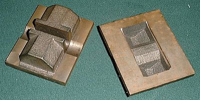
This photograph shows both sides of a D-slide valve. The flat surface
of the valve slides on the valve seat (right photo). In the left
photograph the slot that is cast across the short-centerline of the valve is where the valve rod rests
that moves the D-slide valve back and forth across the valve seat.
Steam pressure holds the valve in place on the valve seat. The recessed
chambers
in the center of the valve (shown in the right photo) directs the passage of
exhaust steam.
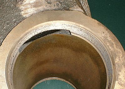
This photograph shows the interior of a cylinder. The end of the
cylinder is threaded so that the cylinder cap can screw onto the end of the
cylinder to seal it off. The slot that is running between the 10 an 1
o'clock is ported to the valve chamber for this cylinder (to one of the two
small rectangular openings in the valve seat shown in the 2nd picture
above). The opposite end of the cylinder is identical to this end;
threaded with a similar slot ported to the valve chamber and to the
remaining small rectangular opening in the valve seat.
This photograph shows the exhaust port for one of the cylinders.
Looking down into the exhaust port you can see the channeling to the
valve compartment and the large center opening of the valve seat. A
similar exhaust port is provided for the second cylinder and both exhaust
ports are connected together with a manifold similar to the exhaust manifold
of an internal combustion engine. To the upper left of the exhaust
port is the steam inlet port to the valve chamber.
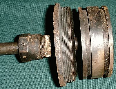
Each cylinder's piston (far right) is cast from two identical halves screwed
onto the end of the threaded piston rod. The end of the piston rod is
then peened over to prevent the piston from loosening on the piston rod.
Each piston incorporates two 1/4" thick rings to seal the piston against the
piston cylinder walls and prevent steam from passing from one side of the
piston to the other (one side will have boiler steam pressure on it while
the opposite side is exhausted to atmosphere). To the left of the
piston is the cap that screws into the end of the piston cylinder.
You'll notice a slight bevel to the edge that is adjacent to the piston.
This bevel helps to direct the steam from the port at the very end of the
cylinder into the cylinder. Attached to the cylinder cap is the
packing journal and journal nut. A graphite packing is placed between
the piston rod and the packing journal and the journal nut keeps the packing
in place. The packing prevents steam from escaping around the piston
rod as it moves in and out of the cylinder cap.
|