|
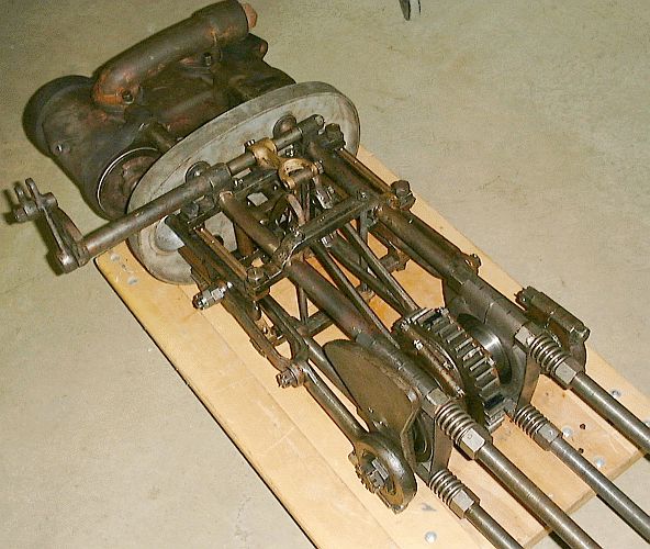
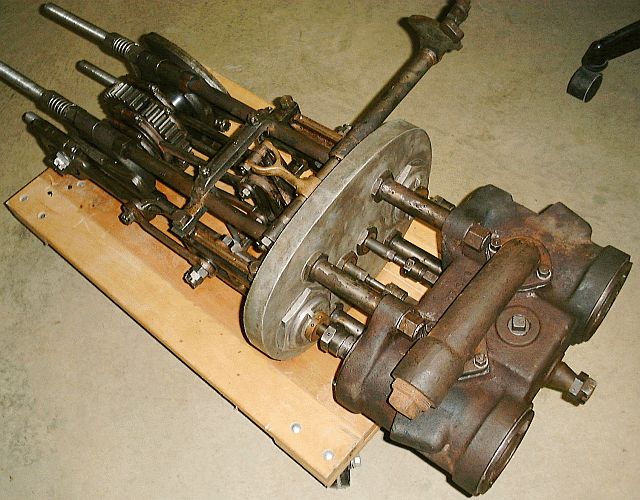
This view of the engine is from the perspective of over the left rear wheel. The four rods at the lower right corner go through the differential housing and mount the engine to the rear axle. The cylinder casting is at the upper left corner of the photograph with the exhaust manifold running across the top of the casting. The rod running off to the center left is part of the valve gear and where the rods from the driver's hook-up pedal attach.
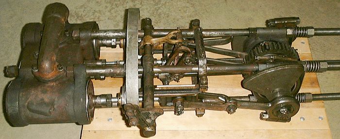
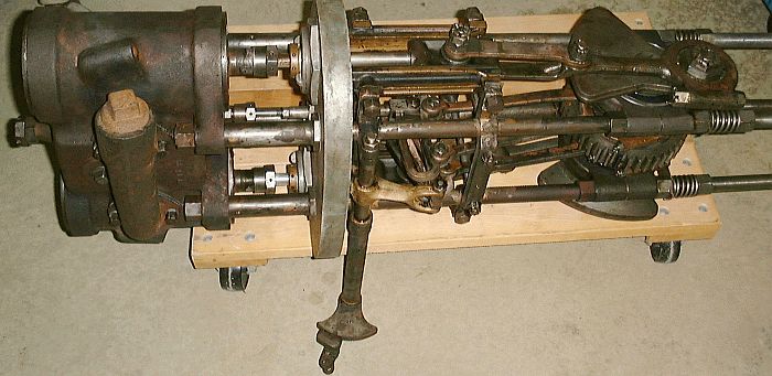
This side view shows all the main components of the Stanley engine.
The cylinders are at the left. The valve and piston rod packing
glands are to the right of the cylinders. The wide band is the
gasket area of the crankcase baffle where the copper cover mates.
The Stephenson Linkage is in the center of the photograph. The
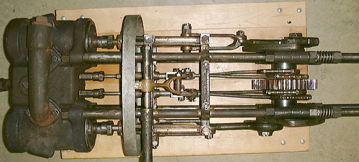
crankshaft with its 40-tooth gear and counterweights is to the right. This top view of the engine clearly shows the four link rods located to either side of the crankshaft gear. In the center of the photograph are the Stephenson Links (located directly under the brass "U") which control the valve action of the engine. Above and below the link mechanism are the crossheads where the piston rods connect to the connecting rods. This view also shows the two cylinders with a square area between that contains the two D-valves that admit steam to the cylinders as well as direct spent cylinder steam to exhaust.
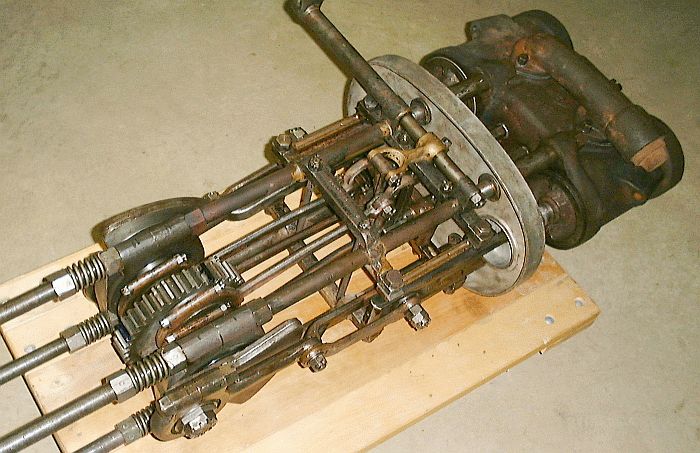
This photograph is from the perspective of over the right rear wheel. The right cylinder's crosshead and wrist-pin connection are shown in detail. Careful examination of the photograph reveals how the four rods provide the frame for the engine. The four rods are held in position by their mounting to the engine cylinder at the right and the cast rear axle housing when the engine is mounted. The rods are restrained from twisting or bending by the casting at the center of the engine that holds the crosshead guides in position. As the major forces of the engine are parallel to the four rods, the engine's strength is designed parallel to the rods.
This close up of the cylinder area of the engine shows the engine hanger stud between the two cylinders. While the engine is mounted to the rear axle, support is still required for the cylinder end of the engine. A laminated steel strap between the engine hanger stud and the car's frame provides support at the cylinder end of the engine. A square pipe plug is in the end of the exhaust manifold. In the top of the valve area between the two cylinders is a second pipe plug which is where the steam supply to the engine is connected through a flexible coupling. The engine is sitting on its left side to show the Stephenson Link for the right cylinder at the center of the photograph. This photograph also shows the packing nuts located between the cylinders and aluminum baffle for the piston and valve rods. The nuts are backed off to gain access to the valve glands which contain graphite packing and prevents steam from escaping at the piston rods. There are also packing glands for each of the rods at the aluminum baffle to prevent lubricating oil from leaking from the crankcase area. |