|
Note to the web site visitor ~ This web page is laid out as if you were reading the instruction manual such that each row of two columns represents the instruction manual laid open for reading. The left and right paired columns on this web page match the right and left pages of the original Stanley document. The vertical rows represent each of the open pairs of pages of the original Stanley document. You should read the web page as if you were reading a book in that you should read the "left page" and then the "right page" and then drop down to the next pair of "pages" as if you had just turned the page of a book. |
FOREWORD There is nothing mysterious about a Stanley car. Its wheels, axles, chassis frame, body, radiator, steering gear, brakes, storage battery and dynamo are similar to other cars. Its power plant and power control are different and are very simple. The power plant consists principally of... A simple two cylinder double acting steam engine, which is attached rigidly to the rear axle, so that the engine and rear axle; in fact, the whole driving mechanism is a unit, attached to the chassis frame at three points. A boiler which supplies steam to the engine. A kerosene burner which supplies heat to the boiler. A set of tanks and pumps which automatically supply water to the boiler, fuel to the burner, and lubricating oil to the engine cylinders. A set of automatic valves which control the supply of water to the boiler and fuel to the burner. A radiator which condenses the exhaust steam and returns the water to the water tank. A storage battery which supplies current for light and for starting the pilot light. A dynamo which automatically charges the storage battery. The power control consists of a throttle lever and a reverse pedal. Mechanical knowledge is not necessary in order to drive a Stanley car successfully, but a thorough understanding of the car will assist one to get the best results under all conditions.
STANLEY MOTOR CARRIAGE CO.,
|
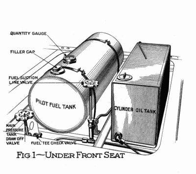 |
Article 2 TO STEAM UP We are going to assume in this article that the car is in the condition it naturally would be in, when delivered by a dealer to a customer, or if it had been running previously. That is, that it has water in the boiler and water tank; fuel in the main and pilot fuel tanks; oil in the cylinder oil tank; and pressure on the main pressure tank and pilot tank. In each detail where we ask you to see that a certain thing is so, if you find it is not so read the paragraph in Article 4 to which we will refer. That will tell you how to make it so. The main fuel tank at the rear of the car has a quantity gauge on the right end. If it contains only a small quantity of kerosene it can be filled now, or after steaming up, as desired. Remove the carpet from the front foot boards, take the hand pump handle from under the ledge of the front seat and put the flat end over the lever through the slot in foot board. Remove the right front cushion and seat board. See Fig. 1 The square tank under the front seat is the cylinder oil tank. If it contains only a small quantity it can be filled now or after steaming up, as desired. To fill it read Paragraph 8 of Article 4. The round tank under the front seat is the pilot fuel tank and has a quantity gauge on top. See that it is more than 1/4 full If it is not, read Paragraph 5 of Article 4. |
|
|
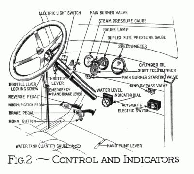
Article 2: To Steam Up (Continued) See Fig. 2 See that there is 30 lbs. pressure on the pilot fuel tank, as shown by the red hand and red figures on the duplex fuel pressure gauge. If there is not, read Paragraph 6 of Article 4. See that there is 100 lbs. or more pressure on the main pressure tank as shown by the black hand and black figures on the duplex fuel pressure gauge. If there is not, read Paragraph 7 of Article 4. The water tank is under the front seat and foot boards and has a quantity gauge extending up through the foot boards. If it contains only a small quantity it can be filled now or after steaming up as desired. The water tank should be filled before it is entirely empty and over flowed a short time to carry off accumulated oil. To fill it read Paragraph 2 of Article 4. Open the engine steam-chest drip-valve, the stem of which comes through the left running board shield. Open the throttle by pushing the throttle lever on the steering post forward. Set the emergency hand brake. Lift the left side of the hood and open the small door in the top of the flue over the boiler. |
|
|
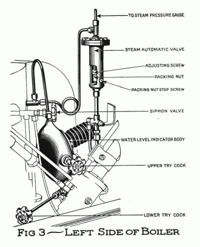
Article 2: To Steam Up (Continued) See Fig. 3 Open the lower try-cock at the bottom of the water-indicator body, which is between the boiler and dash on the left side, and see that water runs out of it. If it does, it indicates that the water in the boiler is above this point, and that is sufficient for steaming up. More does no harm but will take more time to raise steam. If no water runs out read Paragraph 3 of Article 4. |
|
|
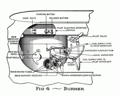
Article 2: To Steam Up (Continued) To Start the Pilot See Fig. 4 Open the door in the left running board shield near the front. Open the peek-hole in the side of the burner casing. Press the starting-button (the long one on the left). Wait 10 seconds. Open the pilot-valve and light the pilot by inserting a lighted match into the peek-hole. If the pilot lights with a strong clear blue flame, shut off the electricity by pressing the release button (the short one on the right). In case the pilot does not continue to burn with a clear blue flame, press the starting button for 2 or 3 seconds, shut off by pressing the release button, and if necessary repeat again. If the pilot flame does not appear strong, with a screw driver turn the pilot screw back and forth quickly a few times. The pilot should burn with a strong clear blue flame 4 or 5 minutes, so as to thoroughly heat the main vaporizer before starting the main burner. Close the peek-hole. To Start the Main Burner See Fig. 2 The main burner starting valve stem goes through the dash at the extreme left above the steering post, and has a wheel handle. Do not confuse this with the main burner valve, which goes through the instrument board, and has a lever handle. On earlier cars the starting valve is in front of the dash attached to the steam automatic. This valve admits gasolene from the pilot tank into the main vaporizer. Open the starting valve one half turn, for one second, close it for three seconds, repeating this until gas comes out of the main nozzles into the mixing tubes, passes up into the combustion chamber and ignites, which it will do with a little puff. Continue opening and closing the valve until the gas, which at first may be wet, becomes dry and almost invisible, then leave the valve open about 2 minutes. Close the starting valve and open the main burner valve using the same method as with the starting valve until the gas is dry, then leave it open. Notice the sound of the little puff the burner makes when it starts and the difference in the sound when the vapor is wet and after it becomes dry, so that when you are sitting in the car and turn on the burner, you will be able to tell by the sound when the burner starts, when the vapor is wet, and when it becomes dry. When steam begins to blow out at the steam chest drip valve, partly close the throttle, so as to keep a small quantity only coming through. |
|
|
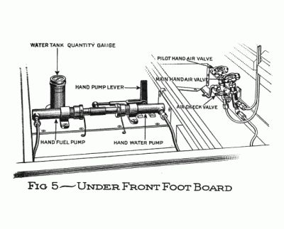
Article 2: To Steam Up (Continued) See Fig. 5 When the pressure on the main fuel falls below 80 lbs. lift the front toe boards and the air pump should be found attached to the air check valve, a fitting between the two hand air valves at the foot of the dash. Open the main hand air valve (the one on the right) and pump 25 strokes of air into the main pressure tank and close the valve. If this has the effect of raising the pressure 50 lbs. or more, wait until the pressure has fallen below 80 lbs. again: then open the valve, pump another 25 strokes of air and close the valve again. Operate the hand fuel pump if more pressure is needed. When the steam pressure gauge registers 500 lbs. close the main burner valve. Close the throttle by pulling back the throttle lever and lock it with the locking screw. Close the engine steam chest drip valve. Close the door in the flue and the left side of hood. See that the pilot light is burning properly and close the peek hole and door in left running board shield. Replace the seat board, cushion, hand pump handle and carpet. Before starting out on the road remember to see that the main fuel, pilot fuel, cylinder oil and water tanks are filled or at least contain sufficient quantity for the distance you are going. |
|
|
Article 3. TO START THE CAR See Fig. 2 Take your place in the driver's seat. The reverse pedal is the one on the left. The hook-up catch pedal has a round end, which extends through the reverse pedal pad. To hook-up the engine press forward on the reverse pedal only, until the catch drops into the notch and holds it in that position. To unhook, press the round end of the catch pedal until the catch lifts and the reverse pedal comes back to its original position. To reverse the engine, press both the reverse pedal and catch pedal forward as far as they will go. Practice hooking up and unhooking until you can readily see when it is not hooked up, but is in full forward gear position, and leave it in that position, driving the car without giving the reverse and catch pedals any thought or attention other than to see that they are in this position. Open the main burner valve a little and listen for the little puff it should make when the burner starts. If the burner whistles, partly close the valve. After a few minutes, when the vaporizer gets thoroughly heated, the valve can be opened more. Release the hand brake. Unscrew the throttle lever locking screw. Open the throttle by pushing the throttle lever forward and close it immediately. Repeat this until the car starts. Open it more or less so as to give the desired speed. To back the car, press both the reverse and catch pedals forward as far as they will go and hold them firmly in this position: Open the throttle and close it again immediately, repeating this until the car has gone as far as desired: Release the pedals and see that they come back to the full forward gear position. While driving, glance occasionally at the pressure gauges to see that the steam and fuel pressures are maintained; at the water indicator to see that the proper water level in the boiler is maintained. The hand should stand nearly vertical, that is, should point half way between high and low: And at the cylinder oil blinker to see that oil is being pumped to the engine cylinders. After you have driven the car a sufficient length of time so that you can drive with assurance, begin hooking up the engine. Always see that the engine is unhooked before opening the throttle to start the car, and hook it up directly after starting. |
|
|
Article 3: To Start the Car (Continued) If you open the throttle with the engine hooked up and the car does not start, close the throttle, press the catch pedal and, if the reverse pedal does not come back, kick it back, or open the steam chest drip valve until the pedal will come back. While driving in congested traffic where sudden stops may often be necessary, it is well to leave the engine unhooked. If while going up a steep hill it should become necessary to stop, hold the car from backing with the brakes and unhook the engine. With the engine hooked up if the car is already moving backward and the throttle is opened the steam pressure may accelerate the motion of the car, instead of checking it, because the steam cuts off so early in the stroke. When the engine is in full forward gear and the car moving backward, if the throttle is opened this would tend to stop the car, provided the reverse pedals were held in position so that the engine could not reverse itself, as it would have a tendency to do under these conditions, and might if the spring were not strong enough to prevent it. Should the pilot go out, vapor of kerosene in the form of smoke would come out around the hood. If this occurs, close the main burner valve and run the car until burner has been cleared of vapor, then relight the pilot. If it has been out so long that the vaporizer is cool, close the pilot valve and follow the instructions in Article 2, To Start the Pilot. When the water tank is nearly empty, if no town water system is available, read the article on The Siphon. |
|
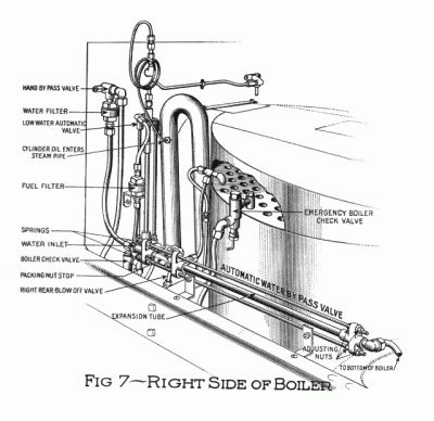
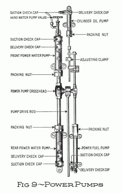
ARTICLE 4. TO PREPARE A CAR FOR STEAMING UP Paragraph 1. When shipping a car from the factory, we usually drain the water system, and in doing so remove the strainer and screw cap from the bottom of the water tank and disconnect the water pipe near the power pumps under the front foot boards (Fig. 9). See that the strainer and cap are in place and the water pipe line intact, from the water tank through the pumps to the feed water heater and from that to the boiler. Paragraph 2 To Fill the Water Tank. The water tank should be filled before it is entirely empty, and overflowed a short time to carry off accumulated oil. Remove the filler cap from the radiator and run water from a hose into the radiator until the water tank under the car fills and overflows. When filling the water tank through the radiator if a large hose is used the water may run back into the feed water heater and engine, and this would be more likely to occur if the car was headed up a grade. If the car is moved with water in the engine, it would be likely to bend or break a crank or connecting rod. To avoid this, leave the brake on and open the engine drip valve and the throttle valve a little and wait until dry steam blows out of the drip valve before starting the car. Paragraph 3 To Fill the Boiler. Use the hose connection furnished with the equipment to connect a hose from a hydrant to the boiler blow-off pipe in front of the boiler on the right. Open the blow-off valve on this line, Open the throttle by pushing the throttle lever on steering post forward. Open the engine steam chest drip valve, the stem of which comes through the running board shield on the left side of the car. The object of this is to vent the boiler so the air can escape when the water enters. Lift the left side of the hood and open the small door in the top of the flue over the boiler. |
Open the lower try cock at the bottom of the indicator body between the boiler and the dash. See Fig. 3 Turn on the water at the hydrant and fill the boiler until water runs out of this try cock, showing that there is sufficient water in the boiler to steam up. More does no harm, but would take more time to raise steam. Turn off the water, close the blow-off valve and disconnect the hose. See that water continues to run out at the try cock after the water has been shut off, showing that the water in the boiler is above this point and not being forced out by the water flowing in. If no pressure water system is available, the boiler can be filled with the hand water pump. To do this: See that there is plenty of water in the tank. Open the hand water pump valve at the front end of the front power water pump. (See Fig. 9.) Close the hand by-pass valve, the right one on dash. (See Fig. 2.) Close the fuel suction line valve between the cylinder oil tank and the pilot fuel tank (see Fig. 1), so as to avoid pumping fuel. Operate the hand pump. See Fig. 5 This pump being seldom used may be air bound. See that the packing nut on the hand water pump is tight. To get the air out draw the plunger out by drawing back the handle. Loosen the union nut at the front end of the hand water pump so the air can escape. Push the plunger in. Tighten the nut and draw out again, repeating until water comes. When you have finished pumping, with the plunger all the way in, close the hand water pump valve; open the by-pass valve, and the fuel suction line valve between the cylinder oil tank and the pilot fuel tank. If the car is handled intelligently there should never be any necessity of pumping water by hand. Paragraph 4 To Fill the Main Fuel Tank. Fill the main fuel tank at the rear of car with kerosene. If kerosene is not available, gasolene may be used. Paragraph 5 To Fill the Pilot Fuel Tank. This is the round one under the front seat. See Fig. 1 If there is pressure on it, be sure the pilot light and main burner valves are closed, start the cap off, and let the air pressure escape. Then take the cap off, and fill with gasolene only, within an inch or two from the top so as to allow space for air. Be sure the gasket is in good condition and the filler cap screwed down tight, so as to prevent any leakage |
|
Paragraph 6 To Pump Air Pressure on the Pilot Fuel Tank. Lift the front toe boards and the air pump should be found attached to air check valve, a fitting between the two hand air valves at the foot of the dash. See Fig. 5 Open the pilot hand air valve (the one on the left) and pump air until there is a pressure of 30 lbs., which will be indicated by the red hand and red figures on the duplex fuel pressure gauge. Close the pilot hand air valve (the one on the left). Paragraph 7 To Pump Air into the Main Pressure Tanks. Open the main hand air valve (the one on the right) and pump 25 strokes of air into the main pressure tank. Then close the valve and, leaving the pump attached, lay it under the toe boards. Now operate the hand pump until the black hand on the duplex fuel pressure gauge shows 140 lbs. Paragraph 8 To Fill The Cylinder Oil Tank. Fill the cylinder oil tank (the square one under the front seat) with Harris superheat steam condenser cylinder oil. See Fig. 1 It is imperative that this oil is used, otherwise injury may be done to the engine, boiler and condenser. It is manufactured by the A. W. Harris Oil Company, Providence, R.I. Paragraph 9. The car now being in proper condition for steaming up, follow the instruction in Article 2. |
THE PILOT LIGHT The purpose of the pilot light is to keep the main vaporizer hot and to supply heat enough to the boiler while the car is standing, to maintain the steam pressure and to ignite the main burner when it is turned on. It is essential that it should burn with a clear, blue flame, as strong as it can be, and not raise steam while standing with full pressure on the pilot fuel. The normal pressure being from twenty to forty lbs. Do not try to see how little fuel you can burn in the pilot, but rather burn as much as you can and not raise steam pressure. You will then probably find that you will have a satisfactory working burner and will use no more fuel, perhaps even less.
|
|
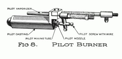
The pilot burner is made up of a hollow casting having slots cut in the upper side of it extending through to the chamber, and a mixing tube which conducts the mixture of gas and air into the chamber, whence it passes up through the slots and burns on top of the casting. The pilot vaporizer is a tube through which gasoline flows on its way from the tank to the pilot nozzle, and a portion of this tube is directly over the casting and in the flame. This heats the gasoline and converts it into a vapor which, passing out of the nozzle into the mixing tube, draws sufficient air with it for perfect combustion. The hole in the pilot nozzle is the size of a No. 64 drill. The pilot screw has a wire in the end of it which goes through this hole and practically fills it. This wire is .036" diameter and is filed off on one side to the diameter of .029". This gives sufficient opening so that the proper amount of gas will go to the pilot burner. If the pilot light is weak with the normal pressure on the fuel, on account of carbon collecting on the wire, turn the pilot screw back and forth quickly. This revolves the wire in the hole and tends to clean it. If this does not give the desired result, shut off the pilot, take out the screw, clean the wire, open the pilot valve for a second or two and blow some vapor through it; then put the screw back and re-light the pilot. The pilot burner assembly can be removed by disconnecting the fuel supply tube and the wires, and taking out the two screws in the plate on the side of the main burner casing which hold the pilot assembly in position. It can then be drawn out. The pilot vaporizer should be set in such a position that the point of the nozzle will enter the mixing tube about 1/8" and should be concentric with the mixing tube. It is customary, if the car is to be used every day, to allow the pilot to burn over night. To do this see that there is fuel in the pilot tank and at least 30 lbs. pressure on it. Also that the boiler contains plenty of water and there is no steam or fuel leak at any point, and that the main burner valve is closed. PILOT STARTING SWITCH In order to start the pilot, it is necessary to heat the vaporizer so as to vaporize the fuel passing through it. That part of the vaporizer which is in the flame is made of a metal having a high electrical resistance, and passing an electric current through it heats it. The starting switch is enclosed in an aluminum case and is located under the left hand running board shield door attached to the chassis frame. The starting button is the long one on the left, and the short one on the right is the release button; pressing this will cut out the current. The pilot valve should be opened within ten seconds after pressing the starting button and as soon as the pilot lights with a good, clear, blue flame, shut off the current by pressing the release button. If the pilot does not continue to burn with a clear, blue flame, press the starting button and release again in a few seconds. |
It is well to conserve the current by shutting it off as soon as the vaporizer is sufficiently heated, and not wait for the automatic cut out to work. The time required for heating the pilot vaporizer depends upon whether the battery is fully charged or partially charged. From five to fifteen seconds should take care of the heating when the battery is reading 1265 to 1275. The switch case cover can be removed, making access to the switch by removing the two knurled nuts and spring washers which set side by side near the push button. Inside the case will be found a piece of metal which is "U" shaped and to which a latch is attached. The "U" piece is a thermostat which deflects and releases the switch due to being heated by the current flowing through it. This thermostat is automatically adjustable to temperature conditions, remaining in operation longer on a cold day than on a warm one and is also affected, to some extent, by battery conditions. The adjusting screw on the latch is for the purpose of regulating the time of operation which is set, here at the factory, to shut off in twenty seconds. Adjustments for timing must be made on a fully charged six volt, 100 ampere hour battery with all connections in perfect condition. If any mechanical adjustment or repairs are to be made, it is advisable to disconnect the positive battery wire at the battery. Care should be taken that every contact carrying the electric current is made up tight. After using this switch, the car must be run at least 25 or 30 miles with lights off to restore the battery. THE MAIN BURNER The main burner is made up of a casting which has a chamber under it. In the top of the casting a large number of small holes are drilled through into the chamber. It has two mixing tubes which conduct the mixture of gas and air into the chamber, whence it passes up through the small holes and burns on top of the casting. The vaporizer is a tube through which the fuel flows on its way from the tank to the main burner nozzles, and this tube is placed over the casting and in the flame. This heats the fuel and converts it into a vapor, which, passing out of the nozzles into the mixing tubes, draws sufficient air with it for perfect combustion. In a steam car the source of all power is the heat produced in the burner. Therefore, a burner in good condition is the first essential, and to give good results, it must have a supply of fuel flowing freely to it under the proper pressure. If the main fire is not good, it indicates that either there is insufficient fuel pressure (the normal pressure for main burner fuel is 140 pounds), or some valve or automatic not open, or a clogging in the vaporizer or the fuel line from the pressure tank to it. See that the small holes in the vaporizer nozzles are clean. If they are not, they can be cleaned by running a small wire through them, after taking out the vaporizer screw. Never use a reamer or broach for this purpose, as it is likely to enlarge the hole. |
|
See that the main burner valve is open. See that the steam pressure is not so high that the steam automatic is closed. See that the low water automatic is not hot. (See Low Water Automatic article.) If there is a clogging in the fuel line, it should be easily located as follows: With all the fire out, take out the vaporizer screws, open the main burner valve, and see if there is a good flow of gas. If there is not, it indicates that the clogging is farther back. Then disconnect the copper tube from the vaporizer at the back of the burner, and try it there. And so on, disconnecting at each union, back in the line, to the main burner valve. Inside of the vaporizer where the fuel enters it, there is a wire cable several feet in length. To remove it, take out the vaporizer clean out plug (see Fig. 4), and with a pair of pliers draw out the cable. If it is too far in, disconnect the union and screw the fitting off the end of the vaporizer. It is advisable to remove this cable once a month and clean it. After removing the cable, some of the particles of scale and carbon will loosen up, and it is good practice to screw in the clean out plug, remove the clean out screws and flush out the vaporizer by opening the main burner valve for a second or two with full pressure on the fuel but with the wire out. There is also a possibility of the small tubes leading down to the nozzles becoming obstructed with carbon, and these can be cleaned by removing the clean out screws and running a stiff wire into each tube. The vaporizer may be blown out with steam by connecting it up with the siphon valve, using a copper tube with two union nuts. The carbon can be burned out of the inside of the vaporizer by the use of an oxy-acetylene torch. To do this, take out the nozzles and all the clean out screws and disconnect the fuel supply pipe to the main vaporizer and screw off the tee fitting on the end of the vaporizer. With the oxy-acetylene torch, heat the vaporizer red hot about 1" from the threads on the end of it. Turn off the acetylene from the torch leaving the oxygen turned on; hold the torch so that the oxygen will blow into the end of the vaporizer and the carbon will ignite and burn on the inside following all the way through it. Keep the oxygen blowing in until the sparks cease to come out at the other end of the vaporizer. When starting the main burner, if the valve is opened too quickly, the rush of liquid fuel may flood the burner. Or, if there is a slight leak in the main burner valve or in the vaporizer, the burner chamber may become filled with a mixture of air and fuel so rich that it will refuse to burn inside. In this case, pump some air into the mixing tubes with the air pump. When the car comes to a stop, or while coasting, and the steam automatic valve closes, the pressure of fuel at the burner nozzles will gradually reduce, so that the fuel will pass out of the nozzles at a very low velocity. Under these conditions, the burner may light back with a slight pop. Then, when the automatic valve opens, the fire may continue to burn inside the mixing tube with a roaring sound. This should not be allowed to continue, as the fire will injure the interior of the burner. Should this occur, the main burner valve should be closed for a few seconds. If one of |
the main burner nozzles becomes partially or wholly clogged up, this is liable to cause a very light popping at the burner nozzles, and they should e made to flow evenly. If the burner lights back with a loud popping, and this takes place often, this would indicate that there is either a leak around the burner casing, a leak in the vaporizer or burner casting, or a leak of steam in the boiler or superheater. See that there are no leaks around the burner casing, that the asbestos between the casing and the boiler is air tight and that the peek hole cover is closed. If the popping continues, generate a full head of steam on the boiler, take off the burner and examine the boiler and superheater. To examine the superheater, run the front wheels up against something immovable and open the throttle so as to get a pressure of steam in the superheaters. If it leaks steam, it should be replaced. If the boiler leaks, it should be repaired, and if the main burner casting is cracked, it should be replaced. The cement used for lining the burner is made up of two parts of The Johns Manville Co. No. 30 long fibre asbestos and one part of The Johns Manville Co. No. 31 high temperature cement mixed into a paste by adding a solution salt and water, one lb. of salt to one quart of water. WATER LEVEL INDICATOR See Fig. 2 and Fig. 3 The water level indicator is made up of a hollow casting; the chamber connected to the boiler at the top and bottom so that the water will stand at the same level in the chamber that it is in the boiler. An arm of the casting extends through the dash and has a dial on the end with a moving pointer. Inside the arm is a small shaft carrying a permanent magnet on the dial end and a cross arm on the inner end. On the long end of the cross arm is a float, on the short end a counterbalance weight. The float is a solid aluminum ball and floats on the water on account of the counterbalance. The magnet attracts the dial pointer so that it shows the position of the float. When the chamber is half full of water, the pointer will stand vertical or half way between High and Low on the dial. When the water rises three inches above the center, the pointer will be at High. When it falls three inches below the center, the pointer will be at Low; thus indicating the water level through a range of six inches. At the center and bottom of the indicator body are try cocks. It is advisable to open these for a few seconds every day to keep the indicator free and clear. The magnet may become de-magnetized, although this does not occur often. In this case, it would be necessary to take off the indicator, disassemble it and have the magnet re-magnetized. |
|
|
POWER WATER PUMPS The power water pumps are the two large pumps located in the pump box, and are driven from the rear axle and operate only while the car is running. Under ordinary conditions, the two pumps throw more water than is required to maintain the water level in the boiler, so that with both pumps running continuously, the surplus water returns to the tank through the automatic water by-pass. Between the automatic by-pass and the water tank there is a hand valve which is located on the right hand side of the dash, known as the hand by-pass valve. This valve remains open, unless for some reason the automatic by-pass fails to work, then the water supply to the boiler can be controlled by the hand by-pass. If it appears that the boiler is not getting sufficient water, see that there is plenty of water in the tank. With the rear wheels jacked up, the engine running and the by-pass valve closed, see that there is no excessive leak through the packing of the plungers, and no leak from any pipes or fittings in the water line from the pumps to the boiler. To see if the pumps are working, slack up a union nut on water pump line near the pump, and if the pumps are working, water will spurt out with great force while the plunger is going in. If it does not, take out the check valves in the pump and clean the valves and seats. Each pump has two check valves, the lower one known as the suction check, and the upper one as the delivery check. The balls and check caps on the suction and delivery are interchangeable. If the pumps do not start working, see that the strainer in the water tank is not clogged. To do this, take out a screw cap in the bottom of the tank and let the water run out; then the strainer can be drawn out. These pumps are packed with hemp packing, and the stuffing box nut should not be screwed down harder than is necessary to prevent leakage. It is necessary to take up on the packing nuts occasionally in case of slight leakage. HAND WATER PUMP See Fig. 5 The hand water pump is located directly under the front floor board, and is the pump nearest the dash. This pump is used only in case of emergency to pump water into the boiler. (See paragraph 3 of Article 4.) In case it should be necessary to pump water by hand with steam pressure on the boiler, close the main burner valve and run the car until the steam pressure is reduced, so as to avoid pumping the water against a high steam pressure. This pump is packed with vulcabestine cord packing, the same as is used in the engine. The packing nut should be turned up only sufficient to prevent leakage. |
|
POWER FUEL PUMP See Fig. 9 This pump is located in the pump box and sets parallel to the rear water pump. Its function is to supply the main pressure tanks with fuel for the main burner. It operates only while the car is in motion, and pumps more fuel than the burner ordinarily requires, the surplus returning to the main fuel tank through the automatic fuel relief valve. In case the power fuel pump becomes air bound, usually a few strokes of the hand pump will free the air as the hand pump forces the fuel through the power pump. There is a shut-off valve in the fuel line, between the main tank and the pump, which is located under the driver's seat. It should be seen that this valve remains open; otherwise no fuel can enter the pumps. Between the shut-off valve and the fuel tank is a strainer, and in case there is difficulty in pumping fuel, examine the strainer. To pack the power fuel pump, first put in a thin leather washer, then three of the special packing rings which we supply for the purpose, and then another thin leather washer on top, and screw the stuffing box nut only as tight as you can screw it with your fingers. If this nut is screwed down too tight, it causes the plunger to cut out the packing. If the fuel pump is properly packed and the nut is not screwed down too tightly, it should not need repacking for a whole season. HAND FUEL PUMP See Fig. 5 The hand fuel pump is located directly under the front floor board. It is the rear one of the tandem hand pumps. Its function is to supply the pressure tanks with fuel while the car is standing. When the plunger is pulled out, it draws the fuel from the tank through a check in the suction line, and when the plunger is pushed in, it forces the fuel through the checks in the power fuel pump, thence into the pressure tanks, registering the pressure on the duplex fuel gauge on the instrument board. This pump is packed with vulcabestine cord packing, the same as we use for the engine, and seldom requires attention, except to tighten up on the stuffing box nut in case of leakage. This nut should be only tight enough to prevent leakage. CYLINDER OIL PUMP See Fig. 9 The cylinder oil pump sets parallel with the forward power water pump, and its purpose is to pump oil from the cylinder oil box, under the driver's seat, into the engine cylinder. The oil flows by gravity into the pump, where it is forced through the oil blinker on the dash, thence through the oil check, and into the main steam pipe, leading to the engine. In case the oil blinker shows that the pump is not pumping, immediately look over the oil line, and if necessary, examine the checks to see that they are free and clean and in good condition. In case the oil check in front of the dash should not hold, allowing steam to enter pump when throttle is open, it should be repaired or replaced. If the tank should run |
dry, the pump may become air bound. To prime the pump, loosen check cap and work plunger back and forth by hand. The amount of oil pumped depends upon the length of the stroke of the plunger. This adjustment is made by moving the adjusting bushing attached to the plunger. To pump less oil, set the adjusting bushing farther away from the pump, and to pump more oil, farther forward on the plunger. Normally, the plunger has a stroke of 1/4 of an inch. A gallon of cylinder oil should be sufficient for from three hundred to five hundred miles. This pump is packed with special packing rings, supplied by us for the purpose. STEAM AUTOMATIC VALVE See Fig. 3 This valve is located in front of the dash on the left hand side of the boiler, and its purpose is to control the steam pressure in the boiler, by closing the supply of fuel to the burner, as soon as sufficient steam has been generated. The tension on the spring determines what pressure the valve will close at. The spring sets against a brass diaphragm and the lower end of the valve stem, which holds the valve open. The steam pressure on the boiler is against the opposite side of the diaphragm, so that when the maximum steam pressure is reached it overcomes the spring, and allows the stem to move up to the seat, which closes the flow of fuel to the burner. As soon as the steam pressure is reduced, the valve opens, and the fuel starts to flow to the burner, and is ignited from the pilot. To carry a higher steam pressure, turn the adjusting screw farther in, and to decrease the steam pressure, back it out. Care should be taken not to turn up the stuffing box nut too tight, as this would cause the stem to bind and might require a considerable variation in pressure to operate it. A satisfactory working steam automatic will operate on a variation of twenty-five pounds pressure or less. To set the steam automatic valve, loosen the lock nut and screw the body up until the valve closes, then turn it back three-quarters of a revolution and set the lock nut. If water leaks through the adjusting screw, it indicates that the diaphragm is cracked and should be replaced. AUTOMATIC BY-PASS See Fig. 7 This valve is located on the right-hand side of the boiler, and the supply tube from the power water pump is connected to the head of this valve, so that when the valve is closed, the water passes into the boiler, and when it is open the water returns to the tank. The valve is operated by expansion and contraction, depending upon whether there is steam or water in the expansion tube. The forward end of the expansion tube is connected to the bottom of the boiler, and the rear or valve end is connected to the top. When the water in the boiler is below the automatic, the steam enters the expansion tube, causes it to expand, and this closes the valve. The water from the pumps must then pass into the boiler, and as soon as the water level in |
|
the boiler becomes higher than the automatic, the expansion tube will fill with water which cools and contracts the tube, and the valve opens, allowing the water supply to return to the tank. The water level in the boiler can be maintained by operating the hand water by-pass valve on dash in case the automatic fails, but so long as the automatic is maintaining the proper water level, the hand by-pass should remain open. The valve stem is packed with hemp packing, and it is advisable to back up the packing nut occasionally and put a few drops of oil on the stem, so that it will work into the packing. There is a strainer in the water line, within a few inches of the automatic by-pass, which should be removed and cleaned every 2000 miles. TO ADJUST THE AUTOMATIC BY-PASS With 100 lbs. steam pressure on the boiler and the water level at the normal height so that the pointer of the indicator dial is vertical, jack up the right rear wheel, see that the hand by-pass valve is open, disconnect the copper tube leading from the side of the automatic by-pass valve back to the water tank so that you can see when the water comes through the valve, run the engine slowly, and see that the expansion tube of the automatic by-pass is cool. If it is hot, it shows that the water level in the boiler is not high enough. When it is cool the water thrown by the pump should pass through the valve freely. Open the right front blow off valve which is connected into the bottom of the boiler in the same line at the front end that the automatic by-pass is. This should have the effect of heating the expansion tube and should close the valve. If it does not, slack up the rear adjusting nuts at the front end of the automatic by-pass rods and take up on the front nuts until the valve closes. Be sure that you leave the blow off valve open long enough so that the expansion tube is very hot. Now shut the blow off valve and pour some cold water on the expansion tube until it is cool and see that the valve opens. If it does not open when it is cool, it shows that you have the adjusting nuts set up too far. Slack them up one square, that is, one sixth of a revolution, and try it again, and see that the valve closes when it is hot and opens when it is cool. The nuts at the back end of the rods, which make a tension on the coiled springs, should be set up so that the valve will close with full pressure on the boiler, and yet have space enough between the coils so that the springs can be compressed at least 1/16 of an inch without coming together. FUEL AUTOMATIC RELIEF VALVE The fuel automatic is located under the foot board back of the driver's seat and its function is to control the pressure on the fuel. Ordinarily the power fuel pump throws more fuel than is required by the burner, and the surplus fuel which is pumped returns to the main fuel tank through this automatic. A stout spring in the automatic holds the valve on the seat until the maximum pressure is reached on the pressure tanks, then the valve |
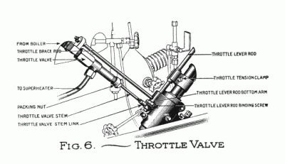
automatically opens. The tension on the spring is made by the adjusting screw, which sets against the spring. To increase the pressure, turn the adjusting screw further in, and to decrease the pressure, back it out. This automatic seldom requires attention. Foreign matter on the seat would prevent it from closing, thus allowing some of the fuel under pressure to turn to the main tank. The seat can usually be cleaned by backing out the adjusting screw so there is no tension on the spring, and by operating the hand fuel pump, but in case this is not effective, the automatic should be repaired. LOW WATER AUTOMATIC VALVE See Fig. 7 This automatic is an expansion valve and stands in a vertical position in front of the dash, and its purpose is to shut off the supply of fuel to the main burner when the water in the boiler gets extremely low. The lower end of the expansion tube is connected with the boiler, and the upper end is connected with the valve. So long as the water in the boiler is above the expansion tube, the valve remains open. Should the water level in the boiler get so low as to permit steam to enter the expansion tube, the heat would expand the tube sufficiently to close the valve, and shut off the fuel supply to the burner, thus warning the operator that the water level in the boiler is low. In case the automatic closes down, stop and determine if possible the cause for it. There are several things that would cause low water, such as a leaky automatic by-pass, the pumps failing to pump due to dirty checks, or tank strainer, no water in the tank, or a leak at some point in the water system. If everything appears to be in good condition, jack up right rear wheel, then close the hand by-pass valve on dash, and run the engine and pumps. If there are no leaks and the pumps are pumping, sufficient water should soon enter the boiler to cover the low water automatic connection. In an emergency case, use hand water pump to pump water into boiler. THROTTLE VALVE See Fig. 6 The throttle valve is located on the left-hand side of the boiler and is connected with the crank on the throttle rod at the foot of the steering post. There should be some tension on the throttle stem when the lever under the steering wheel is in the closed position. There are three prick punch marks on the throttle valve stem which are in line with the port in the sleeve on the stem, and these marks should be in line with the steam outlet to the superheaters. In case the throttle should have a tendency to close itself while running over rough roads by vibration, this can be taken care of by adjusting the tension clamp on the throttle lever rod just forward of the dash. This tension should be set up only tight enough so that it will hold the throttle lever in any position. The throttle is packed with vulcabestine cord packing, the same as we use for the engine. |
|
SAFETY VALVE The boiler is provided with a safety valve which is set to open at 750 lbs. This valve is located on left side of boiler. About the only time that this valve has occasion to blow is when the steam automatic refuses to shut off and the fire continues to generate steam until the pressure in the boiler overcomes the spring in the safety valve and allows it to open. In case this valve should open and does not close readily, rap the end of the stem with the hand pump handle. Should it continue to leak, due to foreign matter lodging on the seat, it will be necessary to have it repaired or replaced. SIPHON VALVE See Fig. 3 The purpose of the siphon valve is to fill the water tank by drawing it in through a hose in case no water pressure is available. It can be used only when there is steam pressure on the boiler. The hose connection to the tank is located inside of the left running board shield door. A hose is supplied with the car and whenever it is necessary to use it, first remove the hexagon cap on the hose connection and slip the hose on. Before opening the siphon valve, drop the end of the hose below the surface of the water, then open the valve and in a few minutes the tank should be full. After filling the tank and removing the hose, see that the cap is put back on the nipple as this keeps it clean. The siphon valve is located in front of the dash on the left hand side of the boiler. In siphoning water, it is good practice not to allow the siphon hose to drop to the bottom of the receptacle holding the water, as this would very likely draw in sediment. This valve should be closed at all times except when siphoning. BOILER CHECK VALVES See Fig. 7 The check valve in the water system just forward of the dash where the water is diverted either to the feed water heater and boiler, or to the water tank, is known as the boiler check. The purpose of it is to allow the feed water to enter the boiler and to prevent it from coming back. When the automatic by-pass is open, the water from the pumps passes forward as far as this check, and returns to the water tank. When the automatic by-pass is closed, the water cannot return to the water tank, so it raises the check, and passes forward into the boiler. In case this check should get noisy, it is probably due to the ball having too much lift, causing it to hammer the seat. Should this take place, either replace it with a new check, or have it repaired. The check valve in the water line near the boiler on the right hand side is the emergency boiler check. The stem which screws into the bottom of the valve holds the cheek off the seat, making it inoperative. The object of having this type of check at this point is to shut off the steam pressure in case of a leak in the water line. Whenever it is necessary to use it as a check valve, simply turn the stem to the left about three revolutions which will allow the check to drop down on the seat. |
FUEL FILTERS In the suction line, between the main fuel tank and the power pump, is a filter. This filter has a thumb screw on the bottom to which a screen is attached. If the pump fails to operate while there is plenty of fuel in the main tank, it would be well to remove this thumb screw, making sure that the screen is free and clear. There is also another filter in the fuel line in front of the dash, which filters the fuel before it passes through the low water automatic. In case of an obstruction at this point, this would be revealed by a poor working burner. In order to clean this filter, it is necessary to drain the main pres sure tank by opening the pressure tank draw-off valve under the right front seat. Then remove and place it in a vise, where is can be taken apart and cleaned. Between the pilot tank and the pilot valve is another filter and in case of an obstruction in this line it would be well to see that this is free and clear. MAIN PRESSURE TANKS These two tanks are located in the fuel line between the pumps and the burner, and are placed just forward of the pump box under the chassis. These tanks have a capacity of about three quarts. Their purpose is to supply the burner with fuel under pressure, and avoid carrying a pressure on the main fuel tank. While running, they are supplied from the main tank by the power fuel pump, and the pressure is registered by the black hand on the duplex pressure gauge on the instrument board. In order to maintain a constant pressure on the fuel while the car is standing, a quantity of air is carried in these tanks as an air cushion. The amount of air required is a matter of volume rather than pressure. In case the hand on the fuel pressure gauge vibrates while running, it indicates that there is an insufficient amount of air in the tanks, and enough air should be pumped in to prevent the hand from vibrating. In case it is ever necessary to draw off these tanks, simply open the draw-off valve provided for that purpose, which is located under the right front seat. This will allow the fuel, under pressure, to return to the main fuel tank. WATER TANK The water tank is suspended from the chassis frame just forward of the engine. The top of the tank is below the bottom of the radiator, so that the condensed steam returns to the tank by gravity. Since there is some oil which finds its way back to the water tank from the exhaust steam, and as the oil floats on top of the water it is good practice when filling the water tank to allow it to overflow, which would carry off any accumulation of oil through the overflow pipe. It is also good practice to fill the water tank before it is pumped dry, as the oil may get into the pumps and obstruct the strainer in the tank, making it necessary to clean it and the pump checks. To take out strainer, remove the drain plug in bottom of tank. |
|
RADIATOR The radiator requires practically no attention, except to see that nothing is allowed to interfere with the free circulation of air through the air passages. Never allow the number plate to hang at a point where it will interfere with the circulation of air through the radiator, as this would reduce the water mileage. The radiator is provided with a safety valve which relieves it of any excessive pressure over three pounds, and should this valve be adjusted to a higher pressure, this might cause the radiator to leak, unless the car is standing with the front wheels lower than the rear, such as standing on a hill and with the water tank full and the radiator is free from water. In cold weather, therefore, it is advisable to avoid this if the car stands in the open for any length of time, to prevent the water from flowing into the lower tank of the radiator where it might freeze. It is good practice to flush out the radiator with kerosene every two or three thousand miles. To do this, drain the water tank and flush it out with water. Then pour a pail of kerosene into the radiator, and have another pail under the water tank to catch the kerosene as it flows out of the tank. Repeat this two or three times, then flush with water. FEED WATER HEATER The feed water heater is the large tube attached to the right side of the chassis frame and extends from the engine well up to the boiler. It serves two purposes, —first, as a feed water heater; second, as a muffler. It consists principally of three parts, —the shell, or main tube, and two water tubes. The steam from the engine exhausts into the rear end of the main tube and leaves it at the forward end, where it passes on into the top of the radiator. The water on its way to the boiler from the pumps enters one of the water tubes and passes back to the rear end, and is transferred to the second tube, where it passes forward into the boiler. This heater seldom requires attention, though in case of leakage in the water tubes the water from the pumps can pass directly into the boiler, by connecting the line from the boiler check valve to the emergency check valve, thereby eliminating the heater until it can be repaired. THE BOILER If the burner is started when there is no water in the boiler, or if it is allowed to run dry with the fire burning, the boiler will become overheated, and when cooled it will contract, and may leak around the tubes. This would not necessarily cause a permanent injury to the boiler, but might require re-expanding and rewelding of the tubes. In case of slight injury, the tubes that leak can be expanded on top and rewelded on the bottom. The expanding is done by driving a taper expander into each tube, first dipping it in oil to prevent adhering to the tube. When the car is left standing with the burner out, and the steam pressure is reduced to zero, the condensation of steam will form a vacuum, which may draw sufficient water from the water tank to fill the boiler. When the boiler is full, it is advisable to draw off two or three gallons before steaming up through the blow-off valve; otherwise if the burner is |
started with the boiler full and should the throttle be allowed to remain closed, the heat would quickly expand the water and create a hydraulic pressure that would run the hand on the steam pressure gauge up quickly and open the safety valve. This can be avoided so long as the throttle and engine drip valve set open to allow vent to the boiler. Should the boiler prime while running, this would allow wet steam to pass into the engine, which would result in loss of power and make the engine pound. This should be avoided, as it may bend an engine crank, or connecting rod, or blow out a cylinder head. In case the boiler primes, first make sure that the hand by-pass valve on the dash is open, so that no more water can enter the boiler. Then open the engine drip valve until the engine runs smoothly again, or stop the car and blow off the boiler for a minute by opening one of the blow-off valves. To test the boiler under cold water pressure, fill it, then operate hand water pump with hand by-pass valve closed until the steam gauge shows the desired pressure. A boiler might "weep" slightly under cold water pressure, though be perfect under steam. Outside of seeing that the boiler is supplied with sufficient water at all times to prevent injury from overheating, it requires no special care except to blow it off frequently, to prevent an accumulation of scale, sediment and oil. We recommend blowing a boiler off once a week, and to open the blow-off valves for half a minute at least each morning to clear the connections and start a circulation through the automatic water by-pass expansion tube. In blowing the boiler off weekly, make sure that both main burner and pilot are out, and open the three blow-off valves on either side of the boiler. Blow off until the water is blown out, and the pressure is reduced to one hundred pounds. This is more desirable than to reduce the pressure to zero. When the steam condenses, it forms a small quantity of chemically pure water, which remains on the bottom of the boiler and tends to re-dissolve any scale that has formed. SUPERHEATER The superheater is located directly under the boiler, and is exposed to the heat of the burner which superheats the steam as it passes through it after leaving the throttle on its way to the engine. It is not attached to the boiler, but is held in place at the rear where it is connected to the main steam pipe, and at the front, where it is connected to the steam tube from the throttle. To remove with burner intact, pull off asbestos, and disconnect the unions at front and rear, then pull it out of burner. When replacing, cover opening in burner with asbestos to prevent air leaks. THE STEERING GEAR The steering gear is of the worm and gear type, and has three adjustments in case of wear. First, to take up on the end thrust bearings of the worm, turn down the large nut at the top of the housing. To do this, loosen all parts that are clamped to the steering post because the post tube turns with this nut. Second, to bring the worm and gear nearer together, turn the eccentric bushing, the end of which protrudes through the chassis frame |
|
and has two slots in it so that a spanner wrench can be used if necessary. Before this eccentric bushing can be turned, loosen the set screw with lock nut, which is located just back of the centre of the steering gear housing. Third, to take up and thrust on the gear shaft, turn in the screw with the lock nut attached on the inside end of the housing, opposite the end of the shaft. In making any of these adjustments, care should be taken not to get them too tight so as to make the gear work hard. There is a plug in the side of the housing which should be removed occasionally to see that the housing contains sufficient oil to properly lubricate the gears. For this purpose, we recommend the use of a thin graphite grease or heavy lubricating oil. A steering gear, properly adjusted and well oiled, will require very little attention. FRONT AXLE The front axle is a complete Timken installation. The bearings should be adjusted so there is slight motion to the wheel and kept packed with grease. When properly adjusted and packed in grease, they will run several thousand miles without attention. Should excess looseness develop, it can be removed by taking off the hub cap and turning up on the spindle nut to a point where there is only a perceptible end play left and the wheels turn freely. These bearings must not be adjusted too tight, as this is disastrous to the bearings, even though they are well lubricated. THE ENGINE The packing in piston rods and slide valve stem stuffing boxes should be given attention about once a month. If they are properly packed and adjusted often, so as to keep the right tension on the packing, they may run a season without repacking. When the nuts are turned up to the end of the thread, some packing should be used. Vulcabestine braided cord packing is used for this purpose. The main bearings which carry the crank shaft have horizontal rollers and are adjustable, though seldom require adjusting. The clamps are made in pairs and have shims placed between them to allow for adjustment. The crank pin bearings also have horizontal rollers and these bearings are adjustable. Care must be exercised, in adjusting these bearings, not to have them so tight that they would heat. The crosshead slides are also adjusted by shims. In adjusting the crossheads, the greatest care must be taken not to have them too snug. If they are adjusted slightly loose, no damage would result, though if too tight, serious damage might result. Care must also be exercised in adjusting the wrist pins. These pins simply float in the crosshead bearing and should not be so tight but they can be revolved with the finger when the lock nuts are set up. The engine hanger strap should be kept in adjustment at both ends so there will be no lost motion, but care should be taken not to adjust it too tight. |
All parts of the engine crank except the pistons and valves run in an oil bath and it is advisable to remove the filler cap in the crank case occasionally and make sure that sufficient oil is in the case. Six quarts of oil are used in the case which would measure 1" at the front end below the filler cap opening. Felt bands are placed around the diaphragm and axle housing to keep the case oil tight. (See cylinder oil pump and lubrication articles.) To remove the engine, pull off the exhaust hose; disconnect the main steam pipe at the packed swivel joint and the reverse rods, take out the engine brace rods and remove the four nuts at the back of the rear axle housing which are attached to the engine front; take off the nut at the top of the engine hanger strap and pull the strap off the stud and let the front end of the engine down; then pull it ahead until it clears the rear axle. The engine should be set so that it is in line at right angles with the rear axle and the gears set so that the teeth are about one thirty-second of an inch from bottom, or as close as they can be and not grind. It is advisable to have the engine case removed every two or three thousand miles and see if any adjustment is necessary. REAR AXLE The rear axle housing is made in two parts bolted together in the center and forms a part of the engine case. The differential has three pinion gears which mesh into the bevel gears attached to the driving shafts. The main drive gear of the differential meshes into the gear on the engine crankshaft. The driving shafts are mounted on Timken bearings next to differential, and S.K.F. Bearings next to the wheels. The adjustment between differential and bevel gears is made by paper shims which are placed between the axle housings where they fit together. In case the differential gear becomes loose, the proper adjustment can usually be made by removing one or more of these paper shims. If all the shims are removed, and yet the differential gear is not tight, the axle should then be dismantled and thin washers placed between the inside bearings and the bevel gears, which will bring the bevel gears closer together, and avoid undue lost motion between them and the pinion gears of the differential. In adjusting the gears, care must be exercised not to get them too tight, which would throw an undue strain on the inside bearings and injure them. The differential and bevel gears, also the inside bearings, are lubricated from the oil in the engine case, which flows back into the rear axle. To remove the rear wheel, take off the dust cap and the castellated nut that holds the wheel on the shaft. Then turn a wheel puller into the hub firmly, turn the screw in the wheel puller up against the end of the axle shaft sufficiently to loosen the wheel. In case difficulty is met with in removing the wheel, strike the end of the wheel puller screw with a hammer, at the same time keeping a tension on the screw, and the jar should cause the wheel to loosen. To remove the outside bearing, take off the dust plate which is attached to the axle with four screws. Then remove the lock nut which is |
|
set up against the taper bushing, and when this lock nut is removed, the bushing can be slipped off the shaft, and the bearing can then be removed. Back of the bearing on the driving shaft is a steel washer and a felt oil retainer. When installing the outside bearings, pack them in grease. It will be observed that there is a coarse thread cut on the outside of the taper sleeve, which fits next to the bearing. This bushing on the left hand side of the axle has a right hand thread, while the bushing on the right hand side of the axle has a left hand thread, and when installing these, this should be carefully observed. To remove the rear axle, take off the spring clip nuts, the perch rod bolts, the engine brace rod nuts and the four nuts on the engine frame rod back of the axle housing. Disconnect the brake rods and wire on the generator. Then block up the engine, the perch rods and brace rods, so they will be supported when the axle is removed. If chain falls are available, use them to raise the rear end of the car by hooking on to the chassis frame in front of the rear seat. If not, place the jacks under the side sills in front of the rear seat. If not, place the jacks under the side sills in front of the rear axle high enough so that the wheels will roll out under the mud guards. The brass rod should have just sufficient tension to stand firmly under the center of the housing. BRAKES The Service Brakes are so called because they are controlled by a foot pedal and are the brakes generally used. They are of the contracting type, consisting of steel bands lined with asbestos fibre. The pedal should have a sufficiently strong spring to hold it back against the sill firmly. When the brake rods are once adjusted to the proper length no further adjustment should be required on the rods, but all the adjustments should be made where the brakes wear, that is, on the adjusting tee band bolt. The levers on the cam shafts, when the brakes are applied, should not pass beyond the center when properly adjusted. The vertical adjusting screw on the brass bracket at the rear should be turned up tight enough so that, when the brakes are off, the bands will clear the drums on the top side. The spring which is attached to this bracket should be sufficiently tight to draw the band up against the casting quite rigidly, though not so tight but what the band can drop down due to the tension on it. This casting can be bent in as close to the band as possible when the brake lining is new so that there will be just clearance enough between the band and the drum to prevent them from dragging. The emergency, or hand brakes, act on the inside of the drums which are of the expanding type and are lined with fibre asbestos. These brakes are adjusted by the right and left hand turn buckle on the rods and by the time the cam shaft levers are past the center, when the brakes are applied, they should be relined. In adjusting the brakes care should be taken that both sets are adjusted evenly so as to apply the same resistance to each of the wheels. |
LUBRICATION It is very important that cylinder oil that is adapted to the condition should be used for lubricating the cylinders and pistons. Any other may cause serious injury to the engine, boiler and radiator. The Harris Condenser Steam Cylinder Oil made by the A. W. Harris Oil Company, Providence, R. I., is particularly suited for Stanley cars having condensers and we would urge each owner to have a supply of this oil on hand at all times and use it exclusively in the cylinder oil tank. For the engine crank case, we recommend the Harris Gear & Transmission Oil made by the same firm. Six quarts is the amount used in the case. This will measure about 1" deep at the front end directly under the filler cap. When it shows 1/2" or less at this point, more should be added. When the oil becomes thick so that it will not splash well or when the color has changed to a brown, the oil should be drained off and replaced with fresh oil. In the large grease cups on the outside rear axle bearings next to the wheels, use a fairly heavy grease; also on the grease cup in the pump box on the cylinder oil pump plunger guide. In the grease cups on the front axle spindle and on the steering rod a light grease should be used. On all other grease cups we recommend the use of a heavy oil. In the steering gear housing a light grease or a heavy oil or a mixture of the two may be used. Once a week the pump drive crank bearing should be oiled. To do this, jack up the right rear wheel and take the plug out of the pump drive crank housing just in front of the rear axle. Turn the wheel until the crank comes around under the hole, then put a teaspoonful of oil on it and replace the plug. ELECTRIC SYSTEM The electric generator charges battery while running from ten to fifteen miles per hour, which registers on the off and on switch on dash. In case the generator does not charge, inspect the wiring, and make sure that all connections, particularly those on battery and generator, are properly made up. If these appear in good condition, inspect generator for dirty commutator. Do not run generator without battery. In case battery is removed from car, connect up the two poles on generator with a wire, otherwise considerable damage may result to the generator. After using pilot switch, make sure that the current is shut off by pressing the short button on the right, otherwise this would cause the off and on switch on dash to clatter and run down battery. Should the lights go out, examine the fuse on the dash under the hood and go over the wiring carefully, making sure that it is not chafed at some point, causing a short circuit. In case the electric system does not work satisfactorily, it is advisable to consult our nearest dealer, or a first-class automobile electrician. |
|
STORAGE BATTERY The battery, when fully charged, should read about 1.285 specific gravity on the hydrometer. 1.180 hydrometer reading is the lowest that can be used with any consideration for starting the pilot electrically. Weekly inspection and filling of battery should be made a rigid rule during hot weather, and after long, hard runs. For ordinary cold weather driving, bi-monthly inspection should suffice. In any case, lean towards the side of more rather than less frequent inspection. Carry the solution about 1/2" over the top of plates. Do not allow this to vary over 1/4" if possible. Keep top of battery dry and clean. If, after using hydrometer, acid is spilled on the battery, wash off same with a strong solution of ammonia and water, wipe dry and cover with Vaseline. If this is not done, the battery may become coated with a while crystal formation, which will act as a conductor between cells and cause a wastage of current. In case of spilled electrotype or loss due to leaky cell, do not attempt to replace same by mixing up your own acid and water. Better consult the nearest battery service station and avoid possible trouble. To replace ordinary wastage, use only distilled water, as the acid does not evaporate. After filling with water, it will be impossible to obtain accurate hydrometer readings until after battery electrotype and water have been thoroughly mixed. This is usually secured only by charging or discharging battery for some little time, although after standing for 24 hours or more a homogeneous mixture may result. The batteries have a positive and a negative mark, as shown by P. and N. Be sure, in putting the battery in the car, that the positive terminal is connected to the wire marked on the terminal and that goes to the pilot switch. The batteries should not be held down to the car in any other way except by two hold-down bolts, which fasten to the handles on the side. Care should be used that the #2 heavy wire and terminals are not twisted, either by hand or by any pressure, when on the battery, as this will loosen up the battery posts which run through the hard rubber, and it will be impossible to keep the battery from leaking at the top. Never run batteries without the covered caps on each cell, and be sure that the vent hole in each of these caps is open. LINING UP WHEELS When a car strikes an obstruction in the road, or runs against the curbing, the wheels are sometimes thrown out of line. This makes the car hard to steer, and has a bad effect on the tires, as it has a tendency to wear them flat. It is good practice to examine the wheel occasionally and see that they are in line. A straight edge is commonly used for doing this, although a piece of cord can be used with equal results. In using cord for this purpose, see that the wheels on one side of the car are in line by having it touch the front and rear wheels at four points just above the hubs. Do the same to the wheels on the other side, and if they are out of line, but three points will strike the cord. They can then be lined up by shortening or lengthening the |
steering spindle lever connecting rod, depending upon whether the front wheels should be drawn together in front of the axle, or spread apart. To draw the wheels together at the front, the spindle lever connecting rod should be lengthened, and-vice versa. This adjustment on the rod is made by removing one of the pins which connect the rod to the spindle lever, and by loosening up the clamp on the yoke where it is attached to the rod, the yoke can be turned on or off, whichever may be necessary. Sometimes it is necessary to bend the steering spindle lever, but this is not done except in extreme cases. WINTER DRIVING For winter driving, fasten a piece of heavy cardboard on the inside of each side of the hood so that it will cover all the openings except the three front ones and will extend dawn about 3/8" below the bottom edge of the hood so as to cover the opening between the hood and the chassis frame. It can be fastened with No. 10 screws and nuts with a good sized steel washer, or a flat steel 1/2"x1/16" to cover the full width of the cardboard. The cardboard should be painted black before installing. Disconnect the copper tube leading from the boiler check valve just in front of the dash to the feed water heater and the one from there to the emergency boiler check, and connect a tube from the boiler check valve direct to the emergency boiler check, thus cutting out the feed water heater. The copper tube leading from the boiler to the steam automatic valve and from there through the dash to the steam gauge, should be filled with a heavy oil, and the steam gauge itself should be taken off and left for a time in a temperature just above 212°, so as to vaporize any water which may be inside it and dry it out before connecting it up to the tube again. The tee sitting on the top of the steam automatic valve contains a bushing with a very small hole in it. The object of this is to retain the oil in the tube leading to the steam gauge and to retard the flow of steam in case the steam gauge should leak or break. The pump drive rod case, the water feed pipe from the pump to the boiler check, and the water by-pass pipe from the automatic by-pass back to the tank, should be covered with asbestos about 1/16" thick. This can best be applied by dipping it into water and covering it with flour paste. After it has dried, paint with asphaltum or other black paint. The pilot light should be kept in such condition that it will burn with a good, strong flame, enough to maintain steam pressure on the boiler while the car is standing. Good clean oil free from water should be kept in the engine case. In earlier models which have the glass water level indicator, the water in the glass and tube leading to it should be replaced with a mixture of glycerin and water or alcohol and water to prevent freezing. |
|
TO DRAIN FOR WINTER STORAGE The copper tube leading from the boiler to the steam automatic valve and from there through the dash to the steam gauge, should be filled with a heavy oil, and the steam gauge itself should be taken off and left for a time in a temperature just above 212°, so as to vaporize any water which may be inside it and dry it out before connecting it up to the tube again. With steam up to 550 lbs. and water in the boiler at the normal level, jack up the right rear wheel, take the cap off the condenser and run the engine slowly for a minute or two. Drain the water tank by taking out the drain plug in the bottom and the strainer, and after it is thoroughly drained replace the strainer and the drain plug. Pour three gallons of kerosene into the condenser and it will run into the water tank. Shut the hand by-pass valve and run the engine slowly. This will pump the kerosene from the water tank through the pipes and into the boiler. As soon as vapor of kerosene comes out through the filler cap of the condenser, open the hand by-pass valve and continue running the engine for a minute or two with the main burner on until steam is raised to 550 lbs. Turn off the main burner and pilot light and see that the pilot is out. Blow off the boiler through a hose into a floor drain or elsewhere so that the vaporized kerosene cannot come in contact with anything that has a painted or varnished finish. After the boiler pressure is down nearly to zero, open the throttle, engine steam chest drip valve, siphon valve and all blow off valves so as to clear out all water. Take off safety valve and shake the water out of it and replace it again. Oil in the engine case should be examined and if there is any indication of water in the oil replace with new oil. Car should be jacked or blocked up so as to relieve the tires of the load. For care of the electric storage battery, read instructions furnished by the battery manufacturers. In earlier models which have the glass water level indicator, the water in the glass and tube leading to it should be drained. |
MISCELLANEOUS Keep enough pressure on the pilot fuel tank so that the pilot light will burn with a good, strong blue flame. Remove pilot screw every day and wipe off wire. Blow out pilot vaporizer once a week with steam by connecting up with siphon valve, removing lower screw in vaporizer before steam is turned on. Blow out main vaporizer occasionally with steam and pull cable every 1000 miles and clean. Keep vaporizer nozzles clean. If hand on fuel gauge vibrates, pump some air into pressure tanks. Open right front blow off valve for a few seconds each morning to start circulation through water automatic by-pass. Blow off water indicator every day for a few seconds. When main fire is on, as when steaming up, keep throttle open if possible, to preserve superheater. When running engine with wheels jacked up remove radiator cap and do not replace cap until radiator has cooled. Blow boiler down weekly. Don't allow water tank to run too low, and clean strainer once a month. Flush out water tank when filling by running tank over slowly. Clean strainer in water line on dash once a month. Clean fuel strainer in suction line to pump once a month. Examine battery weekly. Keep tires properly inflated. Keep brakes adjusted and test occasionally to see that they are equally effective. Keep radiator safety valve adjusted to open at not more than three pounds. If piston rods blow steam, take up on stuffing box nuts or repack. Use hand water by-pass in case automatic fails to perform its function. Run with engine hooked up all the time except when in traffic when starting from a standstill, and when engine is laboring, such as on hills, in sand, etc. Before stopping always close main burner valve. Use only Harris Superheat Steam Condenser Oil in cylinder oil box for lubricating cylinders and piston. Occasionally remove engine case cap and measure oil in case. The oil should be one inch deep. Screw down all grease cups every 500 miles and oil generator bearings regularly. Oil pump drive crank bearing every two hundred miles. |
| Checklist for Operating a Stanley Steam Car - Robert E. Wilhelm Jr. | |
| Stanley Model 735 Color Piping Diagram (Legal size) | |
BACK
![]()
![]()
![]() FORWARD
FORWARD